Saw Blade Terminology
| a1 | Rake angle (hook) | a6 | Front shear angle | EXP | Expansion slot | CSK | Countersink hole |
| a2 | Back clearance angle | D | Diameter | T | Number of teeth | OW | Outer wiper slot |
| a3 | Radial side angle | B | Kerf | SP | Silencing port | IW | Inner wiper slot |
| a4 | Tangential side angle | E | Thickness of saw body | KN | Key slot (width x depth) | P | Tooth pitch |
| a5 | Top bevel angle | d | Bore | PIN | Pin hole | PCD | Pitch circle diameter |
Saw Blade Speeds
| Suggested Cutting Speeds in Metres / Second for TCT Saw Blades According to Material | |||
| Softwoods | 45 – 90 | Raw MDF | 50 – 80 |
| Hardwoods | 45 – 70 | Laminated MDF | 60 – 80 |
| Exotic Hardwoods | 40 – 65 | Rigid Plastics | 15 – 50 |
| Raw Particle Board | 50 – 80 | Soft Plastics | 30 – 60 |
| Laminated Particle Board | 60 – 80 | Pure Aluminium | 50 – 80 |
| Plywood | 50 – 80 | Al – Mg – Cu Alloy / Profiles | 50 – 70 |
Important Notes:
- This chart does not include the maximum safe speed.
- An industry expert must be consulted for maximum safe speeds.
Optimum saw blade speeds are determined by factors which may include the following:
- Moisture content of wood products
- Material feed rate
- Surface finish required
- Material abrasion
Optimum blade speed selection may require the assistance of an industry expert.
General Safety
- Read and retain safety warnings for future reference.
- Incorrect use may cause serious or fatal injury.
- Ensure cutting tool/sawblade, when installed, meets OH&S regulations and standards.
Machine Safety
- Isolate machine at power source before inspecting or changing cutting tool/sawblade.
- Read machine manufacturer’s instructions before installing or using cutting tool/sawblade.
- Machine guards and safety features must be functional and according to regulations.
- Machine specifications, speed and cutting direction must be correct and fit-for-purpose.
- Only install cutting tool/sawblade to equipment where the blade meets with equipment manufacturer’s specifications.
Cutting Tool Safety
- Caution must be used when unpacking and transporting sharp edged tools.
- Inspect for damage. Damaged, cracked or fractured cutting tools/sawblades must not be used.
- Cutting tool/sawblade must be correct type for material being cut.
- Installation of cutting tool/sawblade must be by trained and qualified personnel.
Personal Safety
- Before using the cutting tool/sawblade, always assess your entire task for personal safety and the safety of others.
- Only proceed with task if it can be done safely.
- Use personal safety protection. Respiration protection may be required when sawing some materials.
Cutting Tool Service
- The cutting tool/sawblade must be inspected, sharpened and serviced only by qualified personnel when:
- The power consumption of the machine rises noticeably
- The wear zone of the main cutting edge exceeds 0.2mm
- The surface quality is no longer acceptable
- Inspect for damage. Damaged, cracked or fractured cutting tools/sawblades must not be used.
Grinding of tungsten carbide cutting tools will produce mist or dust containing potentially hazardous ingredients. Safety information may be provided by your supplier.

1. Measure the bore diameter (y)
2. Count the number of pin holes (4 Pin Holes)
3. Measure the pin hole diameter (z)
4. Measure the land between the bore and pin hole (d)
If you send us the above 4 pieces of information we can work out the PCD of the pin holes for you.
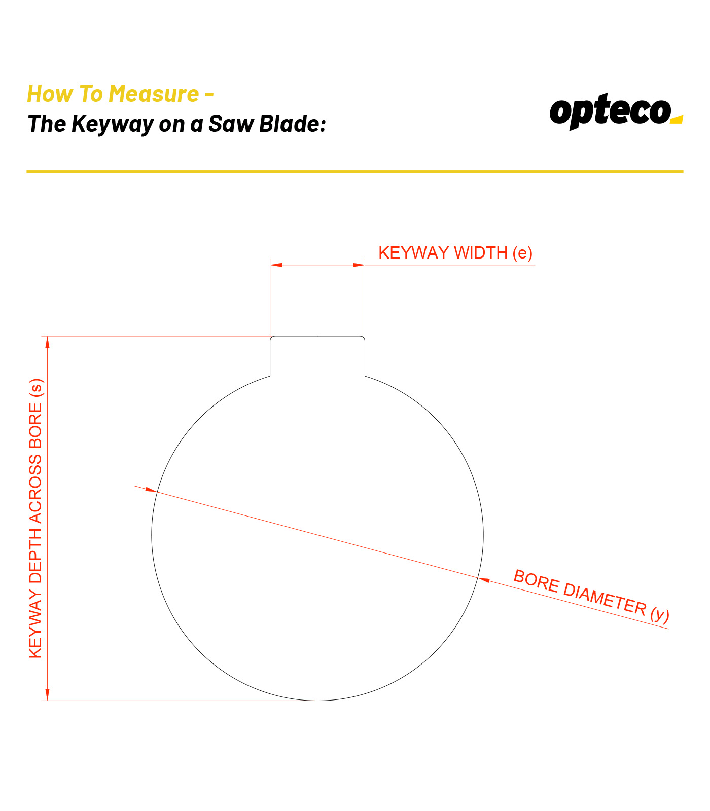
1. Measure the bore diameter (y)
2. Count the number of keyways (1 Keyway)
3. Measure the width of keyway (e)
4. Measure the keyway from the edge of the keyway to the opposite side on the bore (s)
Note that some blades have a set of offset key ways that are rotated by half a tooth pitch. This is common on coarse pitch saw blades so that the all the blades in a bank don’t hit the timber at the same time.
If you send us the above 4 pieces of information we can work out the keyway measurement for you.

1. Measure the bore diameter (y)
2. Count the number of countersunk holes (4 countersunk holes)
3. Measure the pin hole diameter (z)
4. Measure the land between the bore and pin hole (d)
5. Measure across the countersunk hole (x)
6. We need to know which side the countersinks
On the face of the blade with a Direction of cut – Clockwise (shown above)
On the face of the blade with a Direction of cut – Anti-Clockwise (shown on next diagram)
If you send us the above 6 pieces of information we can work out the PCD and countersink details for you.

1. Measure the bore diameter (y)
2. Count the number of countersunk holes (4 countersunk holes)
3. Measure the pin hole diameter (z)
4. Measure the land between the bore and pin hole (d)
5. Measure across the countersunk hole (x)
6. We need to know which side the countersinks
On the face of the blade with a Direction of cut – Clockwise (shown on previous diagram)
On the face of the blade with a Direction of cut – Anti-Clockwise (shown above)
If you send us the above 6 pieces of information we can work out the PCD and countersink details for you.